|
The
manifold injector bungs are 0.530"-0.535" inside diameter [about 17/32" or 13.5 mm]. The fuel supply rail bungs
for the top of the injectors are the same size. Here
are two TBI injectors. One the left is a Holley 85 lb/hr TBI injectors (apparently similar to some Chrysler TBI injectors),
on the right is a GM TBI injector from a 1984 Corvette: Injectors that have
too large a flow rating will make it difficult to tune the engine at idle and cruise. Injectors that have too small a flow
rating can starve the engine of fuel at full power, and seriously damage your engine. To determine how big your injector's
flow rating should be, multiply estimated horsepower (HP) of your engine by the brake specific fuel consumption (BSFC)* and
divide by the number of injectors and the desired duty cycle and you will get a rough estimate of injector size: Injector-Size = (Horse Power * BSFC)
/ (#Injectors * Duty Cycle) for
example, a 135 horsepower gasoline fueled 4 cylinder engine with 2 throttle body injectors and 0.55 brake specific fuel consumption
gives: (135
HP * 0.55 lb/hr/HP) / (2*.85) = ~ 43.7 lb/hr Injectors rated between 42 and 45 lb/hr would be okay in this case. *BSFC is the amount of fuel your engine uses to make 1 horsepower
for one hour. It is usually between 0.42 and 0.58 at wide open throttle. Normally aspirated engines with efficient combustion
processes are at the lower end of the BSFC scale [~0.45], supercharged engines tend to be towards the higher end [~0.55].
you can use the following chart to select injectors based on the total horsepower
of your engine and the total number of injectors: Injectors Rating Required for Specified Horsepower
in lbs/hr and
(cc/min) |
|
Number of Injectors | Horsepower Horsepower | 1 | 2 | 4 | 5 | 6 | 8 | 100 | 59 (620) | 29 (305) | 15
(158) | 12 (126) | 10 (105) | - | 150 | 88 (924) | 44 (462) | 22
(231) | 18 (189) | 15 (158) | 11
(116) | 200 | - | 59
(620) | 29 (305) | 24 (252) | 20
(210) | 15 (158) | 250 | - | 74
(777) | 37 (389) | 29 (305) | 25
(263) | 18 (189) | 300 | - | 88
(924) | 44 (462) | 35 (368) | 29
(305) | 22 (231) | 350 | - | - | 51
(534) | 41 (431) | 34 (357) | 26
(273) | 400 | - | - | 59
(620) | 47 (494) | 39 (410) | 29
(305) | 450 | - | - | 66
(693) | 53 (557) | 44 (462) | 33
(347) | 500 | - | - | 74
(777) | 59 (620) | 49 (515) | 37
(389) | 550 | - | - | 81
(851) | 65 (683) | 54 (567) | 40
(420) | 600 | - | - | 88
(924) | 71 (746) | 59 (620) | 44
(462) | based on 0.50 BSFC and 85% duty cycle
Turbo/supercharged
engines should add 10% to listed minimum injector size
|
Injectors are usually rated in either lbs/hour cc/min. The accepted
conversion factor between these depends somewhat on fuel density, which changes with formulation (i.e., by season), but the
generally used conversion for gasoline is: 1 lb/hr ~ 10.5 cc/min
Another way to select injectors is to take
them from an engine that makes nearly the same power as your engine will [assuming the same number of injectors]. If your regulator is adjustable (many aftermarket
ones are), you can also adjust the fuel pressure to achieve different flow rates. The formula is: new flow rate = old flow
rate × SQRT[new pressure÷old pressure]) So
for example, if you had 30 lb/hr injectors rated at 43.5 psi, and you went to 50 psi, you would get: flow rate = 30 * SQRT(50/43.5)
= 32 lb/hr
Do not run more than 70 psi fuel pressure, or the injectors may not
open/close properly. However,
do not install injectors with a much larger flow capacity than you need. Very large injectors will create idle pulse width issues that will make tuning very difficult. You can estimate your idle
pulse width beforehand. For proper tuning, you will need an idle pulse width of at least 1.7 milliseconds. To calculate the
idle pulse width, recall that the fueling equation for Mega Squirt is: PW = REQ_FUEL * VE * MAP * E + accel + Injector_open_timeSo, find the REQ_FUEL that corresponds to your injector's
flow rate and engine size. There is a REQ_FUEL calculator in Mega Tune, and also here. If you have the engine running , you can check the MAP at
idle (or you can guess - pick about ~25 kPa for a stock cam, ~35 kPa for a performance cam, ~45 kPa for a race cam). Then
you only need the idle VE (and injector open time) to predict the idle pulse width, since this is minimum when there are no
enrichments (E=0, accel=0). Note that you need to use the 'downloaded' REQ_FUEL, which is adjusted for the number
of injectors and their staging. A
good "rule of thumb" for idle VE is 30%. You may actually be 20% or 40% depending on things like compression, overlap,
ignition timing, etc., but 30% will be close enough to give you a good idea about idle pulse width. And use 1.0 msec for the
injector opening time, unless you have a very good reason to do otherwise. For example, on one engine: PW = 6.3 msec * 30% * (33 kPa / 100 kPa) + 1.0 msec = 1.62
msecAnd the measured idle PW was
1.7 msec. So these injectors are okay on this engine, but just barely. If it had been 1.2 or 1.3 milliseconds, these injectors
would have presented very significant tuning problems on this engine. Injectors frequently have identifying numbers stamped on them. You may
be able to identify your injectors by looking on: http://www.geocities.com/MotorCity/Pit/9975/dataBySubject/Injectors.html
or
http://www.telusplanet.net/%7Echichm/tech/injectors.pdfInjectors should not be used at more than
80-85% duty cycle. However, injector rates are always specified at 100% duty cycle and some nominal pressure (usually 43.5
psi = 3 atmospheres). The manufacturer leaves it up to you to determine a system pressure and maximum duty cycle in order
to compute the resulting flow. Injectors
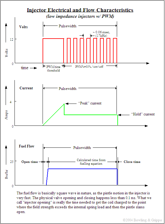
are driven by an electrical signal from Mega Squirt that grounds the +12 volt supply through the injectors to open them. Once
they are open, they flow at a constant rate until closing. The amount of time required to open and close the injectors is
specified in Mega Squirt as the 'Injector Opening Time' (usually about 1.0 msec). Here is an example of a low impedance
injector's pulse voltage, current, and fuel flow:
 Pulse Width Modulation Injectors
are either high impedance or low impedance. High impedance injectors (usually about 12-16 ohms) can take a 12 supply directly,
without a form of current control. Low impedance injectors (generally below 3 ohms) require some form of current limiting.
With Mega Squirt, you can use resistors to limit current, or you can use Pulse Width Modulation (PWM), which is a software
solution built in to Mega Squirt.  PWM works by switching the
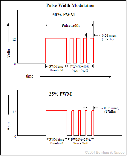
12 volt ground to the injector on and off very rapidly (in about 0.000059 seconds!). The ratio of the "on" time
to the "off" time determines the current through the injectors. However, the easiest way to think of the PWM% is
as a percentage of the supply voltage, so 50% PWM on a 14 volt supply becomes effectively 7 volts on average, 28% would be
4 volts, etc. Remember
that pulse width and PWM% are two different things. Pulse width is the total duration of the signal whereas PWM% is the ratio
of 'on-time' to 'off-time' within the pulse. So in the above illustration, the pulse width for both is the
same, but the PWM% for the first is 50%, while for the second it is 25%. The PWM% you will be able to use depends on the fly back circuit you have.
Version 2.2 hardware generally requires about 55% to 75% PWM. Often the engine will run with lower values, but will not have
enough voltage to re-start. Note that using embedded code version 2.986 or higher will disable PWM during cranking, allowing somewhat lower PWM% values. The Fly Back Board allows you to lower the PWM% dramatically, generally to 30%
or less. It also helps close the injectors faster. With better fly back control, you can reduce injector opening times (recall that the injector
opening time is really the sum of the opening and closing times), and increase the duration of the 'controllable'
part of the pulse width (i.e. after the opening time), The important thing about the injector open time is that it sets a lower bound for the pulse
width (regardless of whether PWM is on, etc.). so if you have injector opening at 1.7ms, you cannot set it to 1.6 or anything
lower, even with VE=0. Mega Squirt assumes no fuel is injected during this time, but some is, though it is hard to calculate
how much. The longer it takes to open, the more fuel is likely injected during opening. With lower opening times (by allowing
full voltage (i.e. no PWM), you can get the injectors open quicker. Your engine will need a certain amount of fuel to run correctly at idle when fully warmed
up. If this amount is below that injected during the injector opening time, you will always be rich and have no way to lean
it out, short of reducing the fuel pressure. Note
that PWM is disabled (in v2.986 code) during cranking so the injectors get full battery voltage. This makes 'severe'
starting conditions (lower cranking voltages, etc.) less likely to result in the injectors not opening. This is not possible
with resistors, unless you devise a way to bypass them during starting (like the older cars did for the ignition coil).
When using low-impedance injectors, which are also called peak and hold injectors (P&H), you wire them in parallel. The
wiring is the same for P&H or saturated [high-impedance]. To exceed the recommended number of injectors (see below) either requires resistors in series with
each injector or a modified fly back setup.
|

