|
Project Boss
302… Update 3; Installation of Moroso Breather 85485 While the second modification
I had to make to the Boss 302. Not real sure if this new engine, the Coyote or in my case Road Runner,
has the same plaguing issues with oil mist as the 03-04 Cobra had or not…but having dealt with that issue for so long,
I did not want to take any chances, so this was the second mod. In all honesty, the 03-04 had a more
complex problem, it definitely had an oil mist control problem. That oil mist was caused by the oil being
flung around inside both valve covers, by the 4-camshafts, 32-Valves, Springs, Rockers and Adjusters, not to forget the chains
and sprockets that the oil liked to ride up and fling all over the place. Oil, and plenty of it on the
valve train is a good thing. But having it too much of it mix with the breathers air flow, is not.
So, let's see what the problem was on the 03-04 Cobra. First for those that may not know, the
03-04 Cobra was also caller the Terminator. It was a 4.6L DOHC Modular engine that was factory supercharged
from Ford, with its high pressure side cooled by a water-to-air inter-cooler. The Filtered air entered
from the passenger side, flowed through the Throttle Body , Intake Elbow and into the Blower (supercharger) from its top right
hand side entrance. The Ambient Temperature Air was pulled through the Blower; compressed, pressurized
and expelled from the bottom directly into the Air -to- Water Inter-Cooler which laid underneath. There
in the lower intake manifold, as the heated air blew through the inter-cooler, the heat was transferred to the water in the
system, which cooled the intake air charge, and that cooler air then flowed out the bottom of the inter-cooler and around
and down into the heads. From there it waited till the intake valve opened, and rushed in to fill the cylinders
with as much cool, pressurized air as possible. That's the theory and operational cycle behind the
system. The problem was the oil mist created in the valve covers was substantial, the air flow from the
breather system connects directly to the valve covers and a hose carries to the intake air system, dumping it into the system
just ahead of the supercharger, and after the throttle body. This fast paced flow brought with it many
small oil droplets that were mixed within the air, and the harder and faster you ran the engine, the more oil it brought.
The first problem was the oil blowing all over the inter-cooler, this would lead to the oil getting sticky and allowing
more and more oil and other contaminates to attract themselves to the inter-cooler, leading to some flow loss and plugging.
Mix, the oil that did not stick to the inter-cooler went on to make it to the heads, this is where the oil would pile
up on the back of the hot intake valves and cook. This eventually lead to caking of the back side of the
valves, to the point that flow was severely hampered. I have taken a part some heads with as much as
3/4-1" crust of burnt oil lining the back of the intake valve, resulting in about 25-40% flow loss strictly through
blockage. This also got on the valve seem, which lead to problems there like sticking valves and still
a lot of oil mist made it into the cylinder to turn to cake or oil coke. Not wanting to dwell on an different
engine and subject, but this activity took its toll on these cars, by slowly robbing performance, causing mechanical issues
and de-creasing fuel efficiency.
With some back history, maybe now you can appreciate the concerns I had, as well as many other new
engine owners out there. SO, let's get started. The Moroso company makes many different
Air/Oil Separators, for many cars, and some 5-6 for the late model Mustang itself. The device is very well
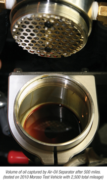
made and is tasked with simply removing the oil from the air stream that flows through the separator. On
the bottom, there is a very small holding bin, it holds some 3-4 ounces of oil. To drain, simply turn the
flow valve a quarter turn and allow the oil to drain out, you can place a drain hose on the end of the fitting, permanently
or removing it when not needed. I would think that is your going to go thru the trouble of installing one
of these, you might as well plan on installing with a permanent drain hose, which ends in a convenient location under the
separator itself. Use an end cap to plug the hose when not in use, this will keep it free of debris and
insects.
Working on this modification does not require any kind of under car work, so no lifts, jacks or other
dangerous activity is needed. Just park the car in a comfortable place to work, set the brake and place
in park. The first thing you will have to do is un-bolt the engine cross-over brace that runs from the
two upper front suspension mounting locations, as we will need to mount the Separator on the passenger side using the same
mounting point and bolts that fastened the cross-over brace.
The mounting bracket supplied in the
kit, comes bare metal. I painted mine a textured silver metallic color as I had some paint handy.
I would plan one painting the bracket, it would take no time till it was covered in rust if not. You
could use a body color to match the paint on the car/ Or something close or contrasting, like the Stripe
color of engine color. Once that is painted and dried, you will want to pre-assembly the bracket to the
separator before mounting it to the car.
The Mounting bracket (steel one), is used to hold the supper nice polished aluminum separator mount, by two small screws
that pass thru the steel bracket and into the back of the aluminum mount. There is also a single screw
that is used to tighten the aluminum bracket on the separator, simply install the screw and leave loose. Now,
assemble, and tighten. Before the separator is mounted up, we need to add the fitting you will use
for the in and out air hoses, plus the drain assembly that screws into the bottom of the separator assembly. The
fittings included are standard brass 90° barb fittings, I changed things up a bit and used some nice Black AN
fittings, you do as you wish, for there is a great opportunity to add some individual creativity here.
Once that is done, you can place the separator into the aluminum mount and alien so the top of the separator is about
two (2) inches from the top of its mount, now tighten the socket head Allen bolt. You should have the aluminum
mount holding the Air/Oil separator two (2) inches higher then itself, and that assembly mounted to the steel bracket.
The steel bracket goes on the first or closes to the front of the car and engine, mounting stud. I
didn't like the way it looked, so I added better washers and nuts before finishing here. I also put
an extra washer under the other stud so the Cross-Over Brace sat more level, you can do as the instructions say or as I suggest.
Now, you can re-install the cross brace if you removed it, or simple tighten everything back down. This
is what mounts the separator and it's carrier to your car, pretty simple and effective.

|
| Moroso Breather/Oil Seperator Kit |
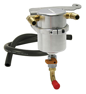
This is a file photo of the kit, as you can see it comes with Tank, Mounting Bracket, Tank Clamp Ring and some push in Brass
Fittings and about 36" of black Rubber Hose. This is adequate to do the job, however I wanted the
installation to look a little better, so I went with AN8 Black Fittings and Black Hose. The factory ends
that connect to the engine are re-used. You simply remove them from the factory hose and push on to your
new hose. On my hoses, I used Red Shrink Tube W/hot glue inside to keep everything air tight and looking
nice. You do not want a vacuum leak.
  Kit comes with everything needed to install breather
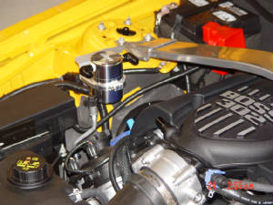
tank, but I used AN Fittings for this installation. Here you see the tank mounted to the passenger side strut tower. You simply
loosen the strut tower brace and slide the bracket under one of the tower bolts. I did use some washer to lever the bracket
back out once the tank bracket was installed. You see the 2-AN8 90° fittings installed in the tank, I used them to get
the hose assembly away from the fender wall. Also, make sure when you mount the tank, that the aluminum
bracket that holds it has the beveled side down. You have to look at the inside of the clamp, where is
a groove or bevel there.

|
| Tank mounted on the passenger side strut tower |
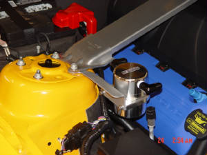
Close view of Breater Assembly mounted
to Strut Tower. Notice now level the Bracket, Tank and Cross Brace are. You will have to shim the mount to get
this.
Here, you see the factory Hose Assembly removed from the Valve Cover Connection and the Intake Connection. That
Hose was removed and the Factory Ends taken from it and re-used for the new hoses.
This is the new Hose Assembly complete with Factory Connector attached. Notice the use of Triple Wall Shrink
Tube to seal up Connector Ends.
Again, the Factory Connector was removed from the Original Hose Assembly and Connected
to this AN8 Hose. This picture shows us connecting the new end to get a accurate measurement from the Intake
Manifold Connection to the Tank Fitting it will connect to. The Factory ends are very easy to remove, simply
push in on the connector release and pull off. To remove the Connector from the Factory Hose Assembly,
you need to carefully slice thru the hose with a razor blade, but not so deep you cut into the connector itself.
|

